Sig J-3 1/4 Scale Cub Build Series – Part 12 – Wings and Wing Tube
Category : Model Airplane Building , Model Airplane Reviews
Since the Sig Quarter Scale cub is an older kit I decided I wanted to “modernize” the wing design by incorporating a bolt on fuselage center section, wing tube, and a two piece removable wing. The original design called for the center section to be permanently attached to one of the wing halves. I did preserve the functional wing struts for this build however.
To begin the wing design I had the plans scanned at my local UPS store so I could work off an image of the plans using a program called DevWing. Many builders in this hobby are familiar with the “Profili” program offered by the same company. https://www.devcad.com/eng/devwing.asp
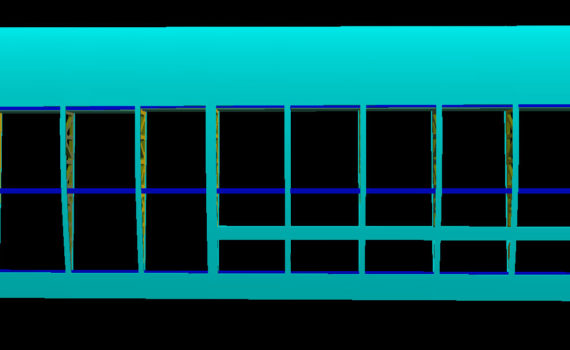
DevWing is a great program that allows you to completely design a wing with spars, wing tubes, dihedral, servo boxes, and even multi-part wings just to name a few of the features! I started by basing the design off of the scanned sig plans and drew in the positions for the aileron and spar locations. I also used some basic trigonometry to build in 1.75 degrees of dihedral into the wing. (A little dihedral in a cub is a good thing giving stable flight characteristics and also prevents the wing from looking like it’s “drooping” in flight compared to a completely straight wing with no dihedral.)
DevWing also allowed me to specify the wing tube locations and it automatically accounts for the dihedral I had specified. I decided to make the first three ribs incorporate a wing tube from TNT Landing Gear. I used their 5/8″ by 30″ long aluminum tube with a .049 wall thickness and socket.
Another thing I decided to do was build in two degrees of washout into the wings. DevWing allows you to configure this and builds the washout into the building tabs it creates for each rib. This allows you to build the wing on a flat surface without the need for a wing jig! Washout will prevent the wing tips from stalling as quickly as the center of the wing toward the fuselage – helping to reduce the chance for the dreaded tip stall. (NOTE: the test flights with this built into the wing have been extremely stable and without event. Landings and take offs are very graceful and smooth!)
DevWing also allows you to lighten the ribs by automatically generating cutouts into the ribs. This really helps to keep the weight down and doesn’t compromise strength. It also serves to make running servo wires much easier. With the DevWing program you have complete control on how much material the program is allowed to remove. I used 3/16 balsa – which is a little thicker than stock. Using the thicker ribs will make up for an deficit in strength and wider balsa is easier to work with while building the wing on the bench!
Once the wing is fully designed (you can preview a 3D view of the wing from any angle as you build so you can get a good idea of what is looking like) DevWing provides an export feature allowing you to take your parts to the nearest CNC machine for cutting. (A couple of years ago I invested in one of the eBay CNC machines – so far it’s been reliable and has worked really well! You’ll have a lot of fun with all the precise parts you can make!)
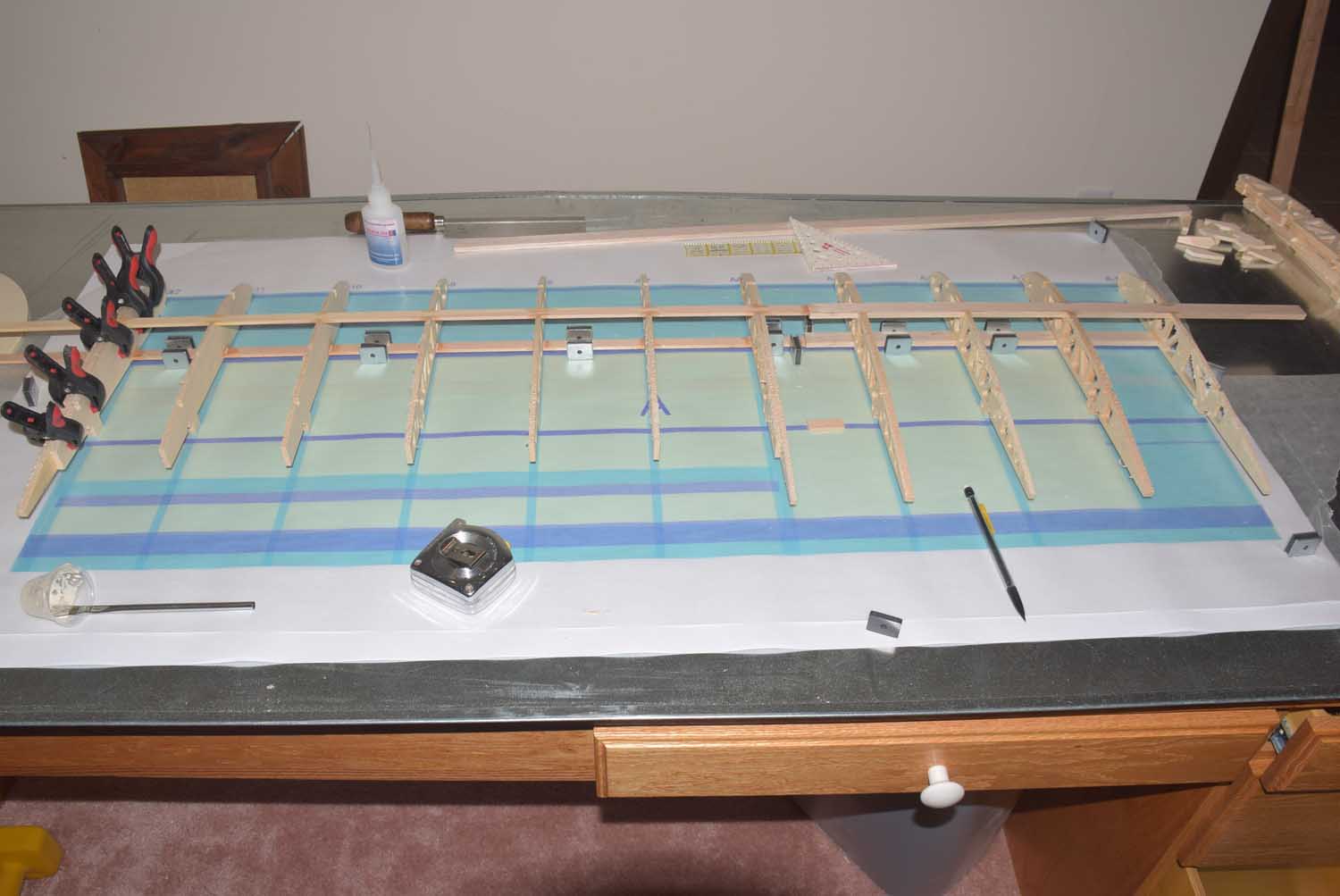
Once all the parts were cut out I began the building process on my magnetic work bench. I’ll spare you the detailed description of building the wings since the process is the same for most wings. Just remember that the flatness and straightness of the building surface will determine how straight and precise your wings are.
I normally start by laying down the bottoms spars in place and securing them with magnets to keep them from shifting around. Next I start by placing the ribs in one by one – dry fitting them to ensure a good fit before any glue is added. Once the ribs are in place I’ll glue them with CA making sure to use a square next to each one to make sure it’s perpendicular to the spar and lines up properly on the plans. With the ribs securely in place I’ll put on the leading and trailing edges. Finally I top things off with the top spars. Once that is all dry I then add in the shear webbing which greatly increase the strength of the wing at this point. Once the spar webbing is dry I sheet the top and bottom using the traditional D-tube construction method. Once the sheeting is in place the wing is very stiff and strong – just the way we want it!
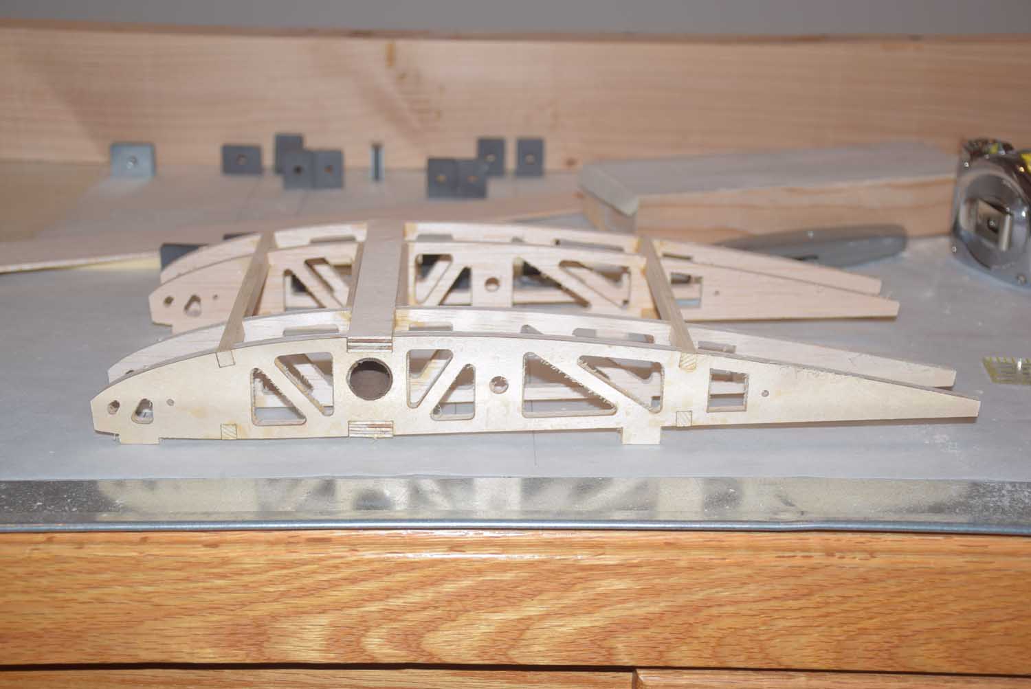
Here’s a gallery of photos of the building process!
-
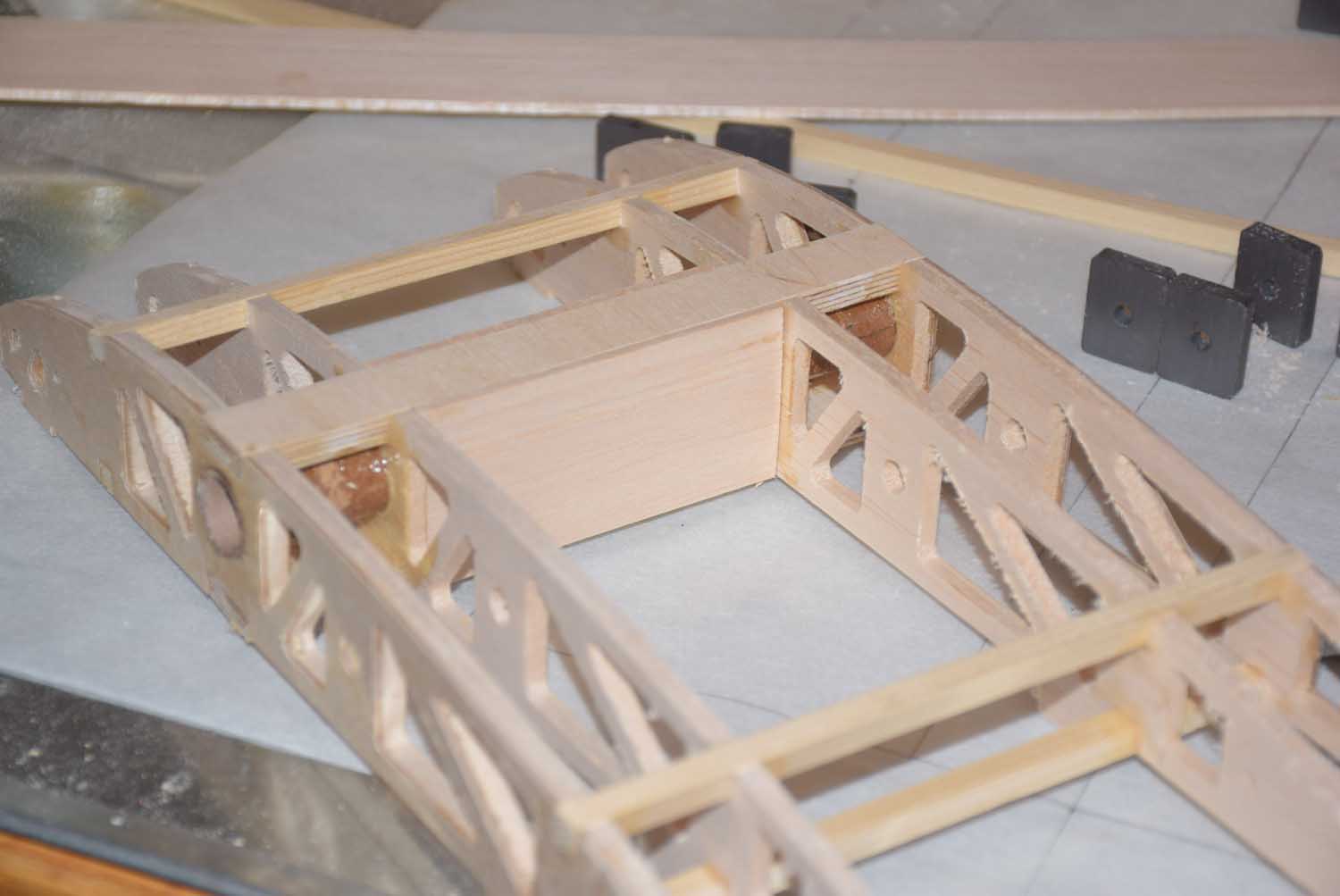
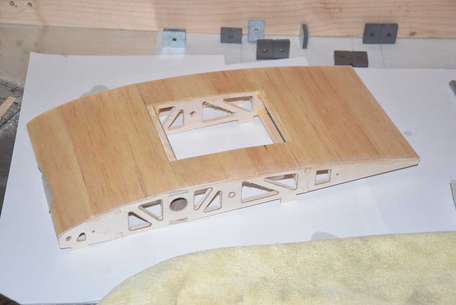
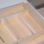
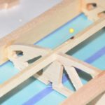
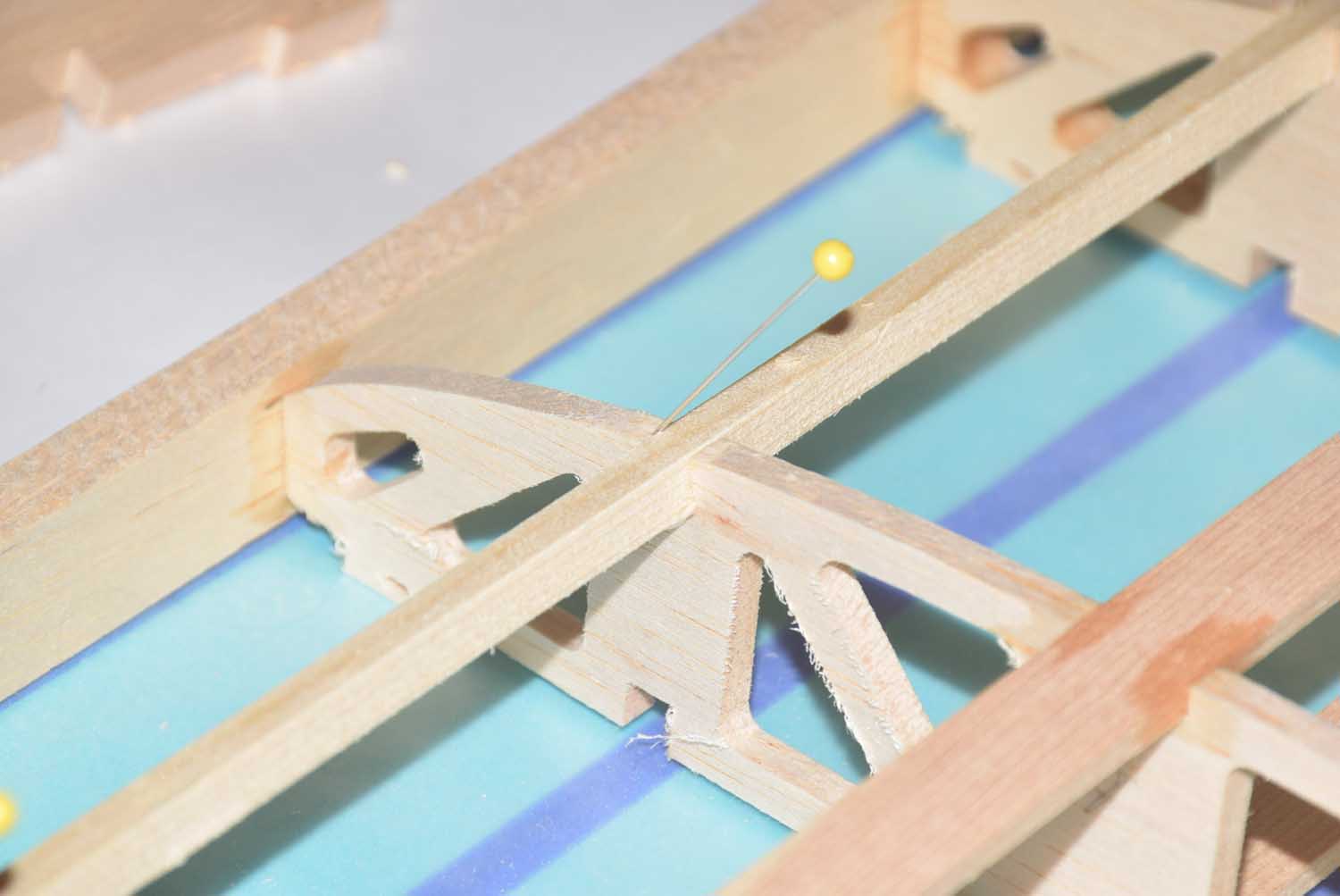
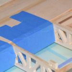
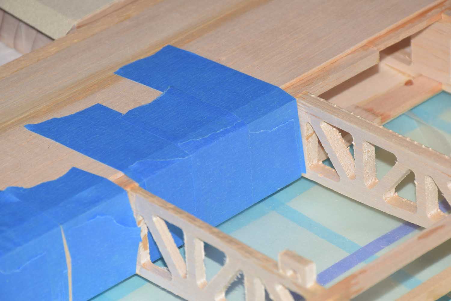
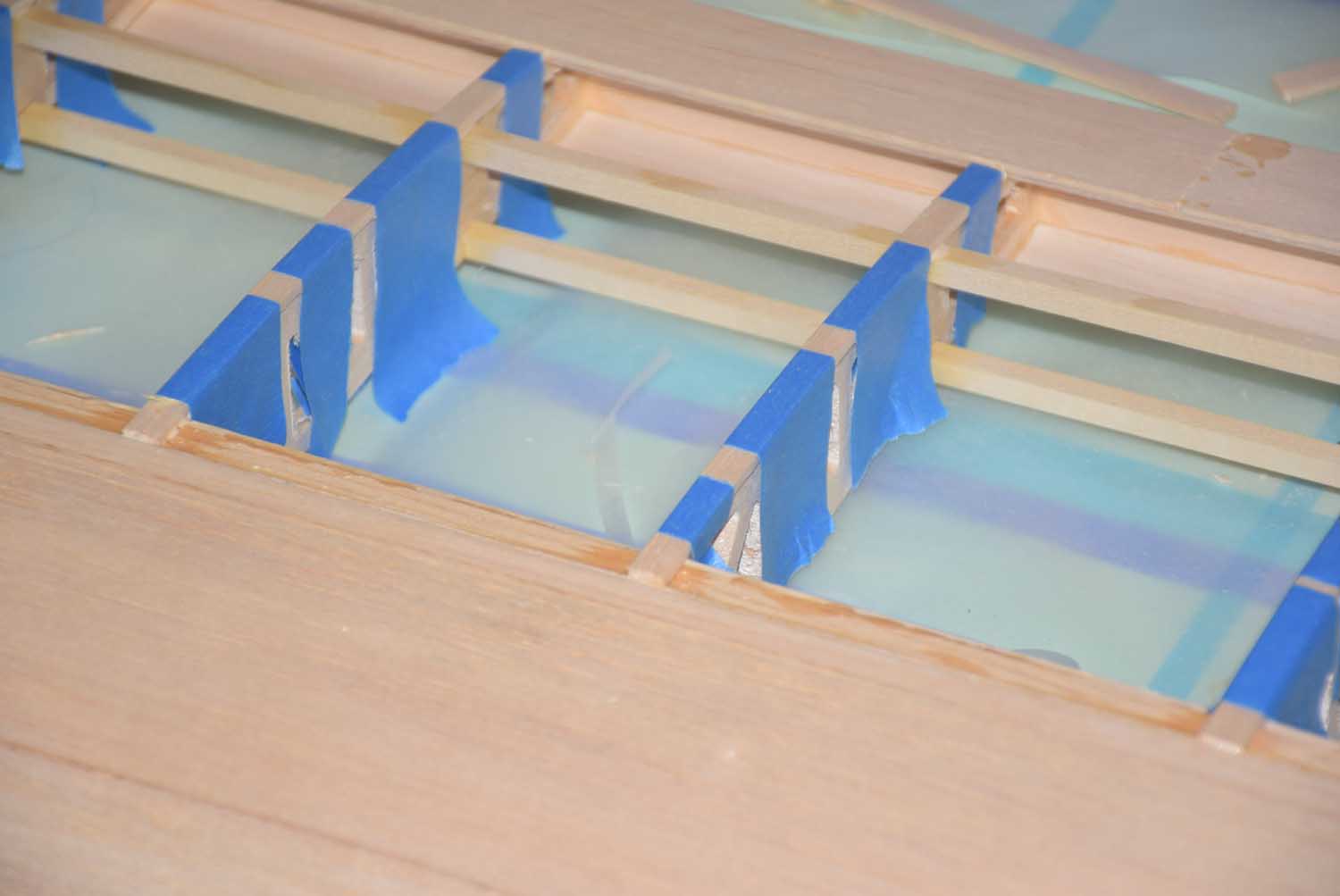
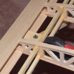
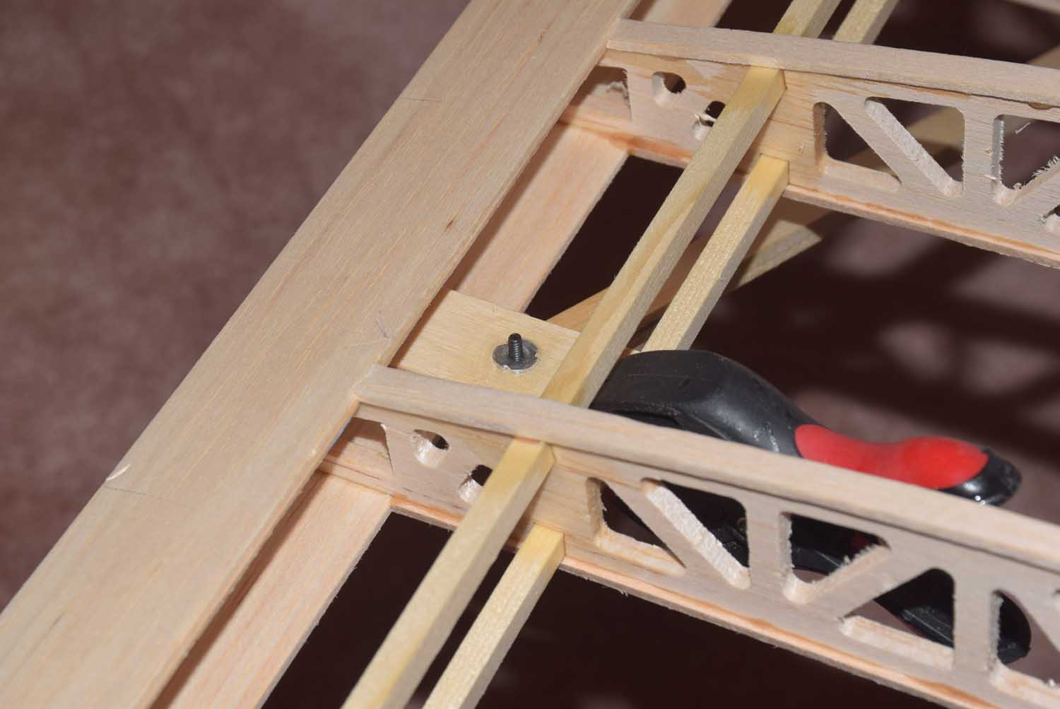
- Wing Tube placement and framing
-
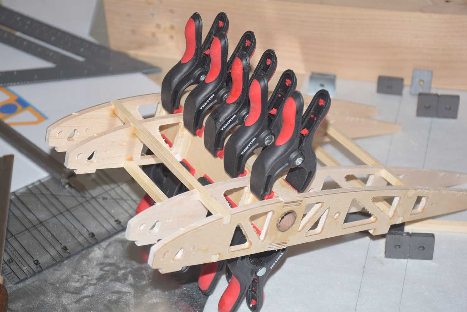
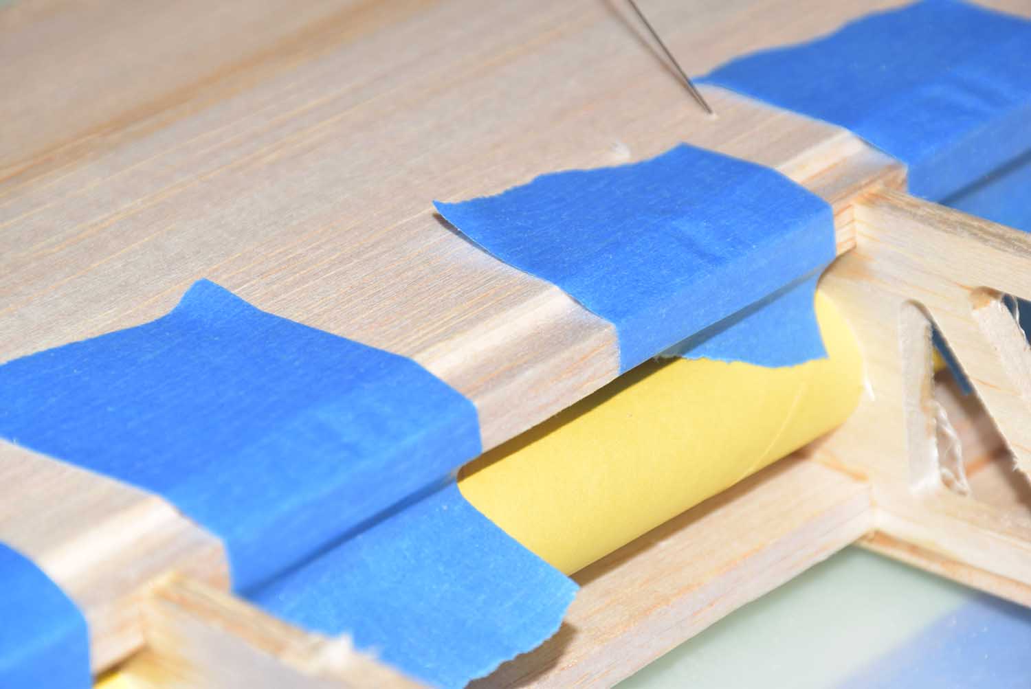
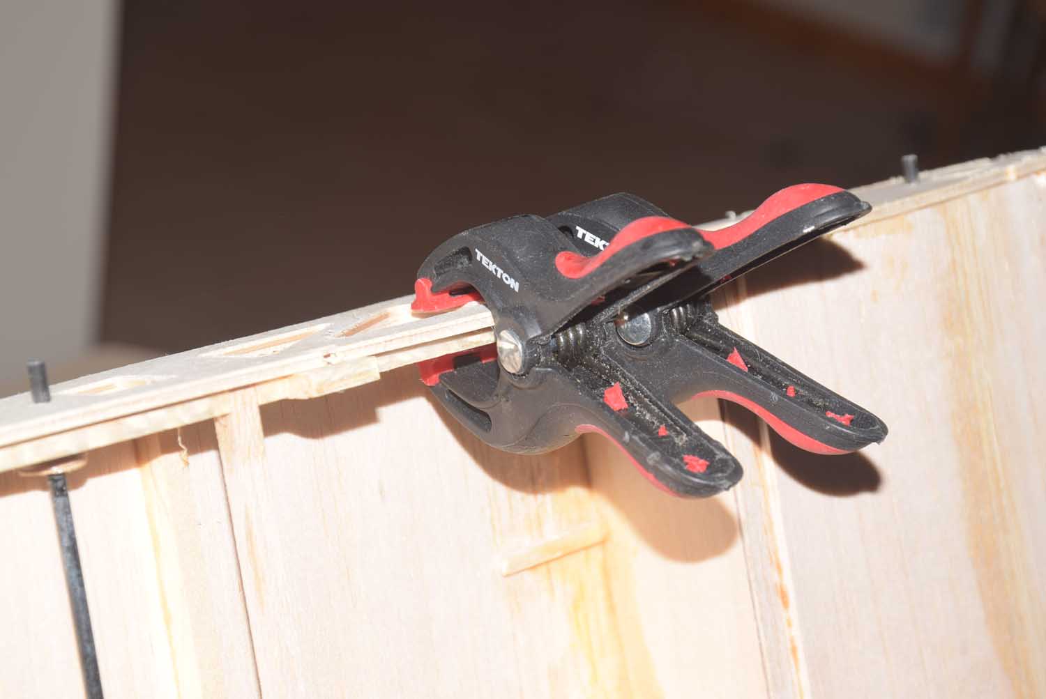
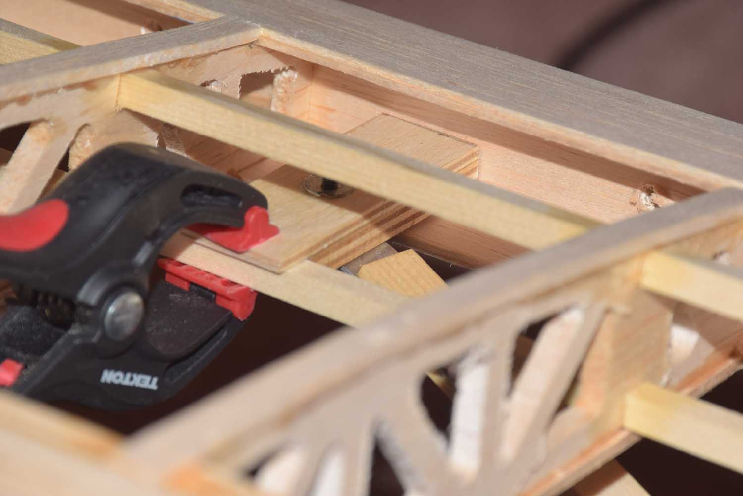
- Clamping 1/16 ply spar webbing in wing tube area for added strength
-
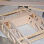
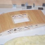
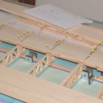
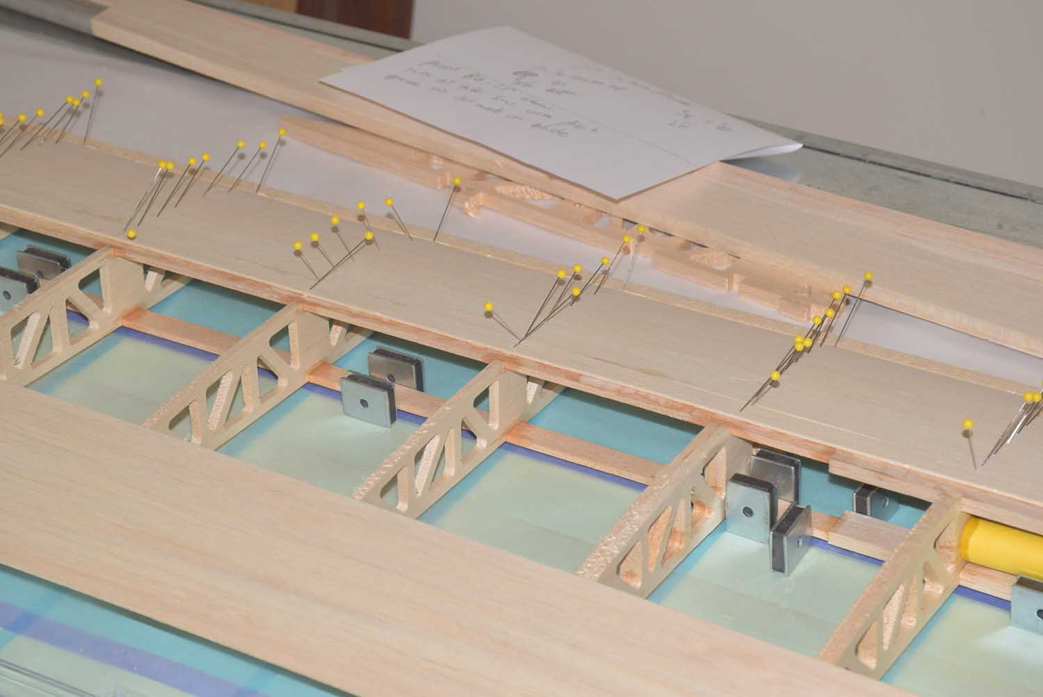
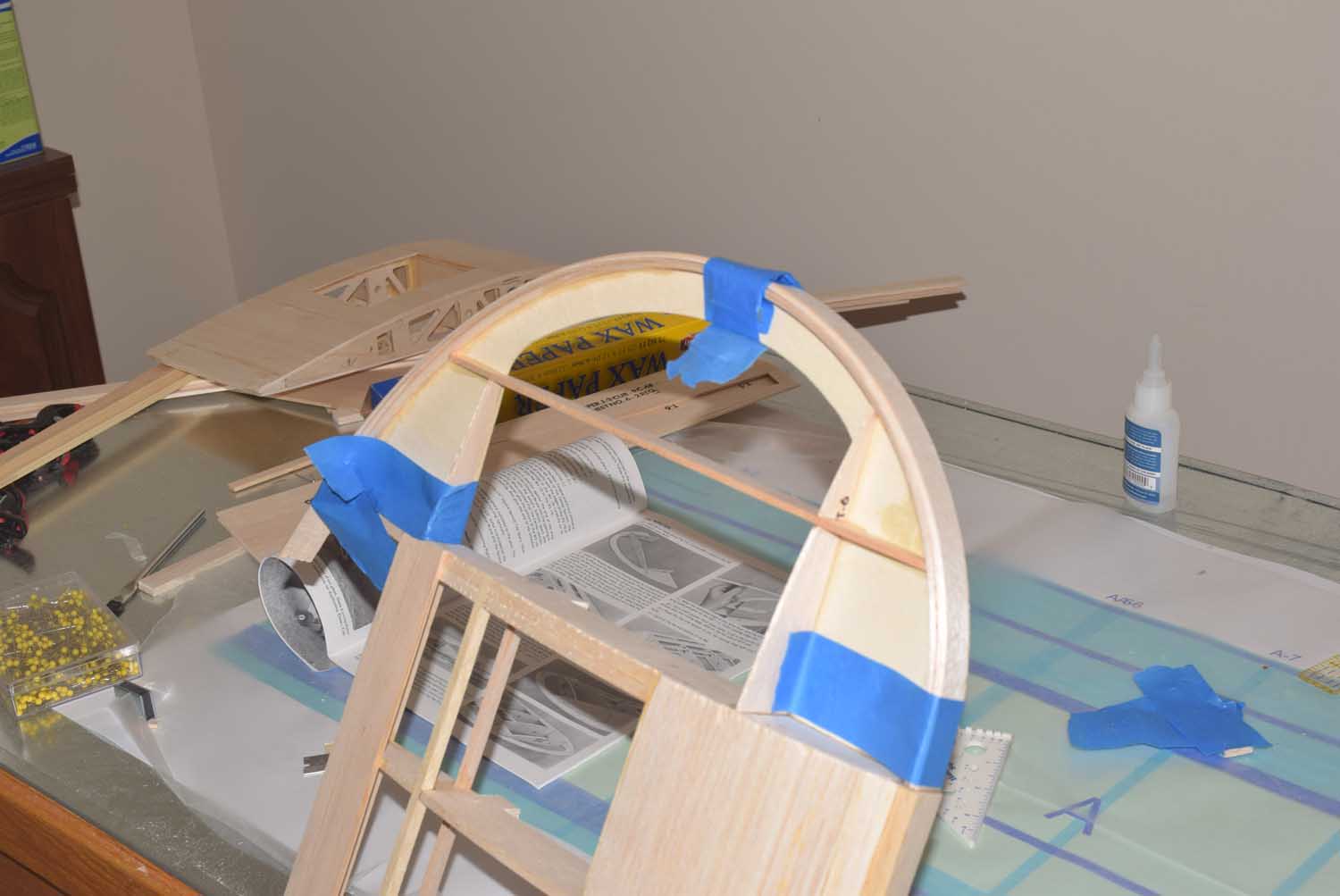
- Continuing framing up of the bolt on center section.
-
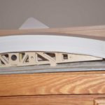
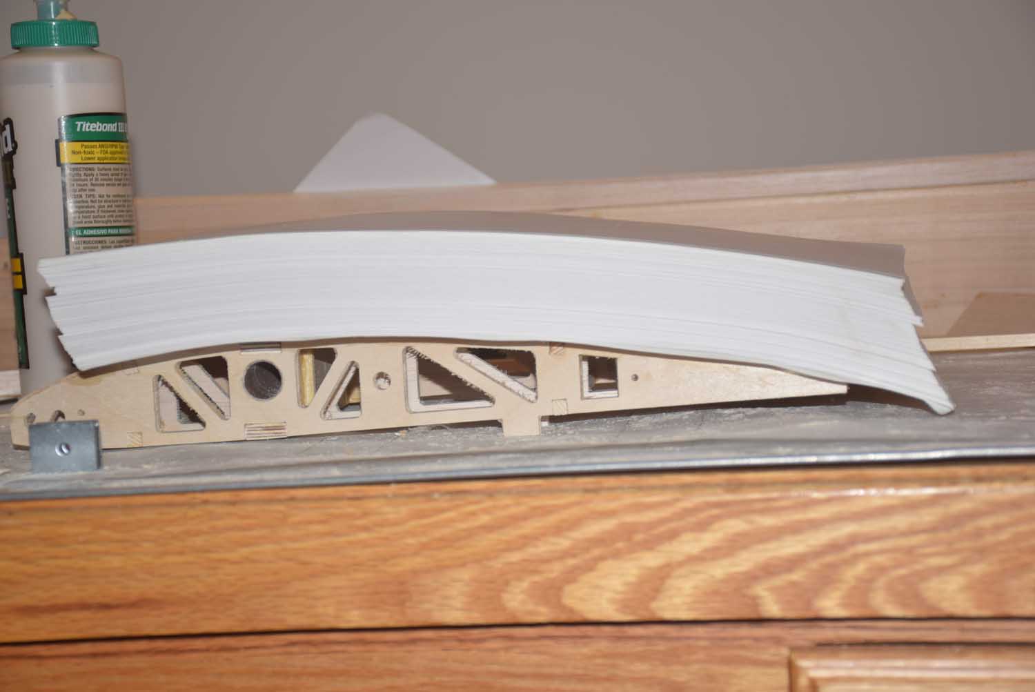
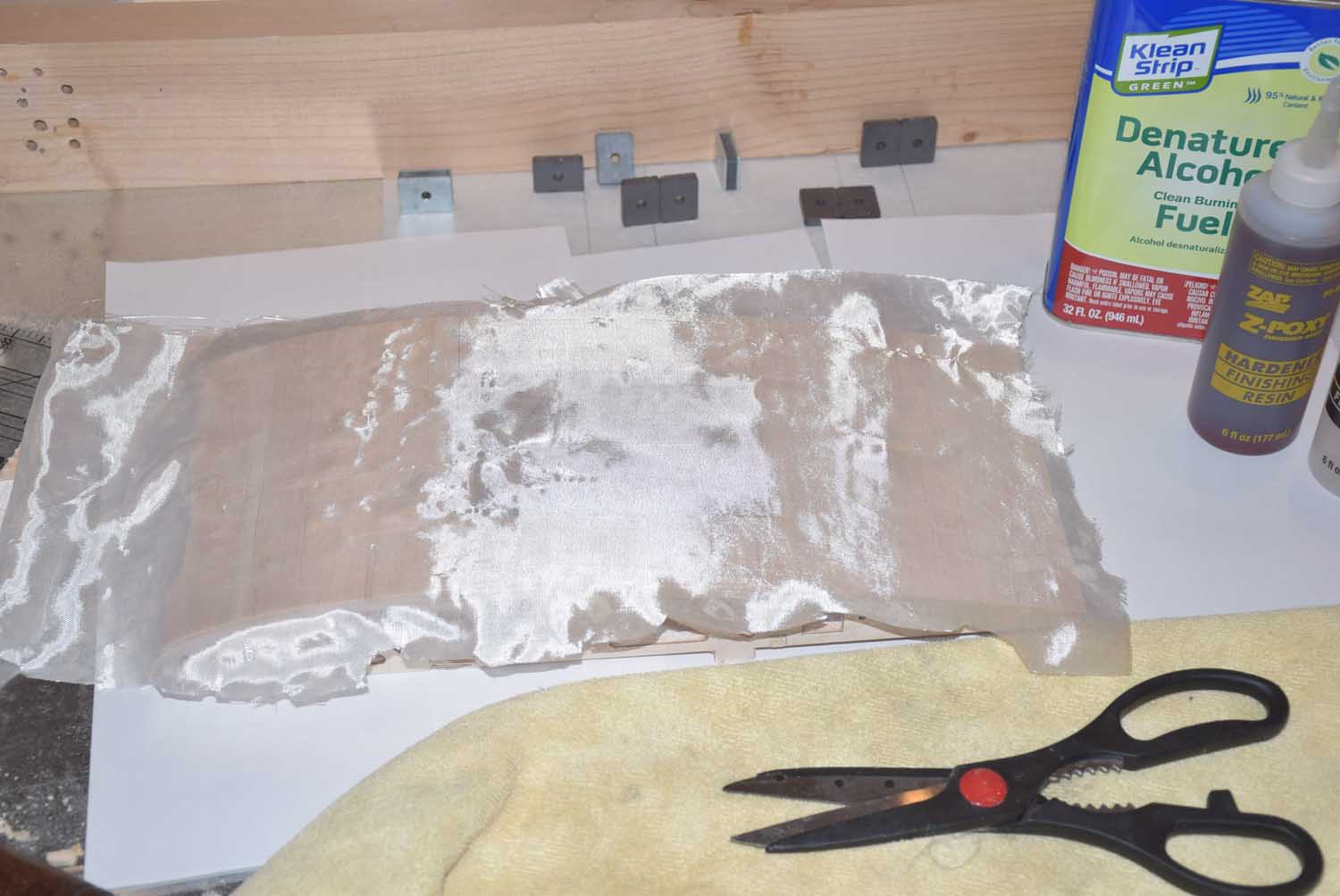
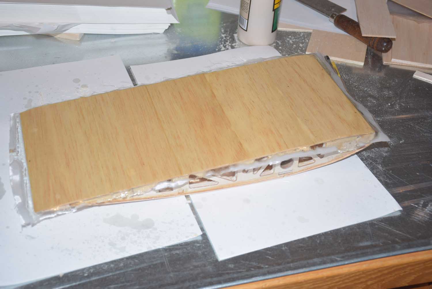
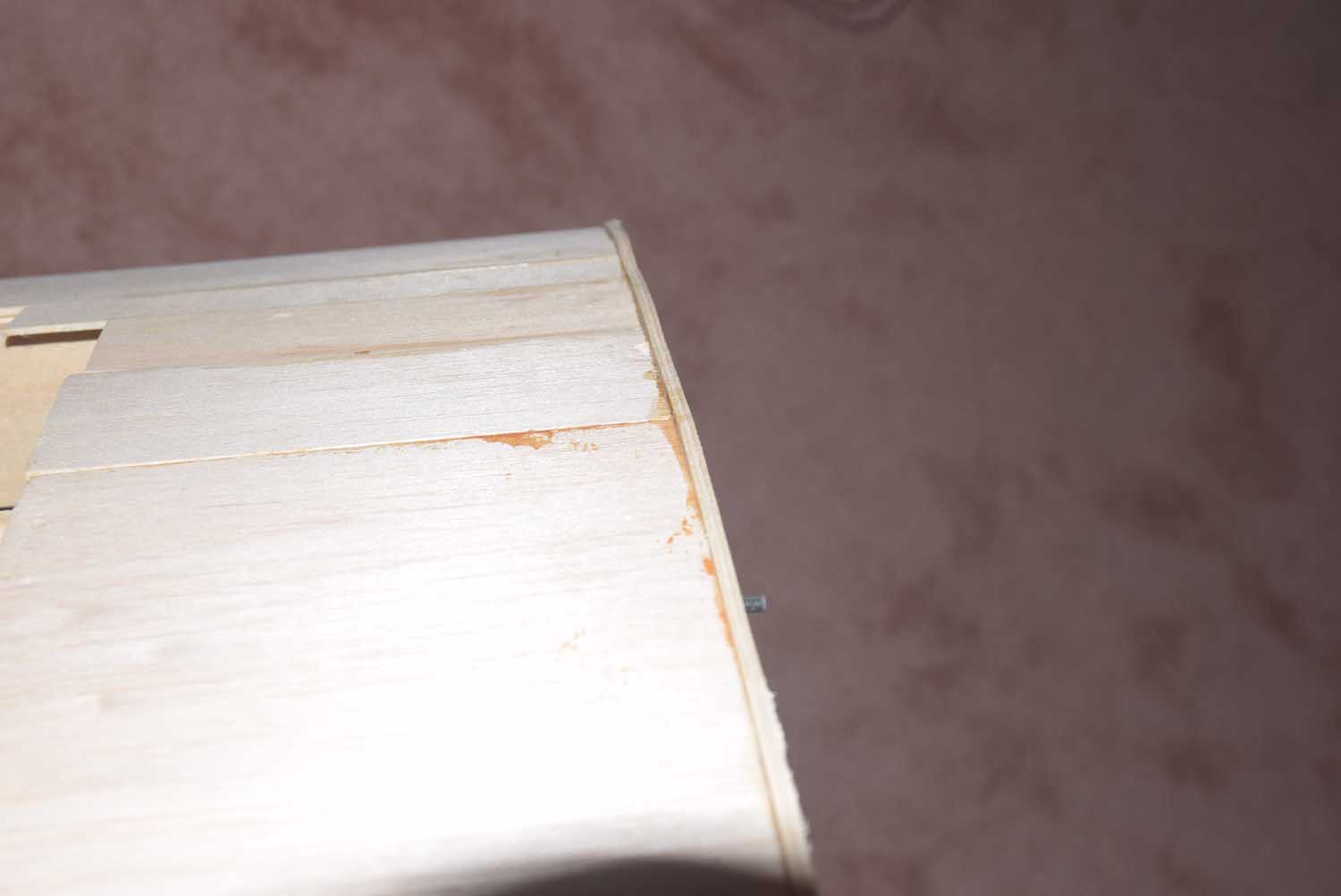
- First layer of sheeting on top. The first layer will be covered with fiberglass and then a second layer will just remain as balsa so I can cover with iron covering.
-
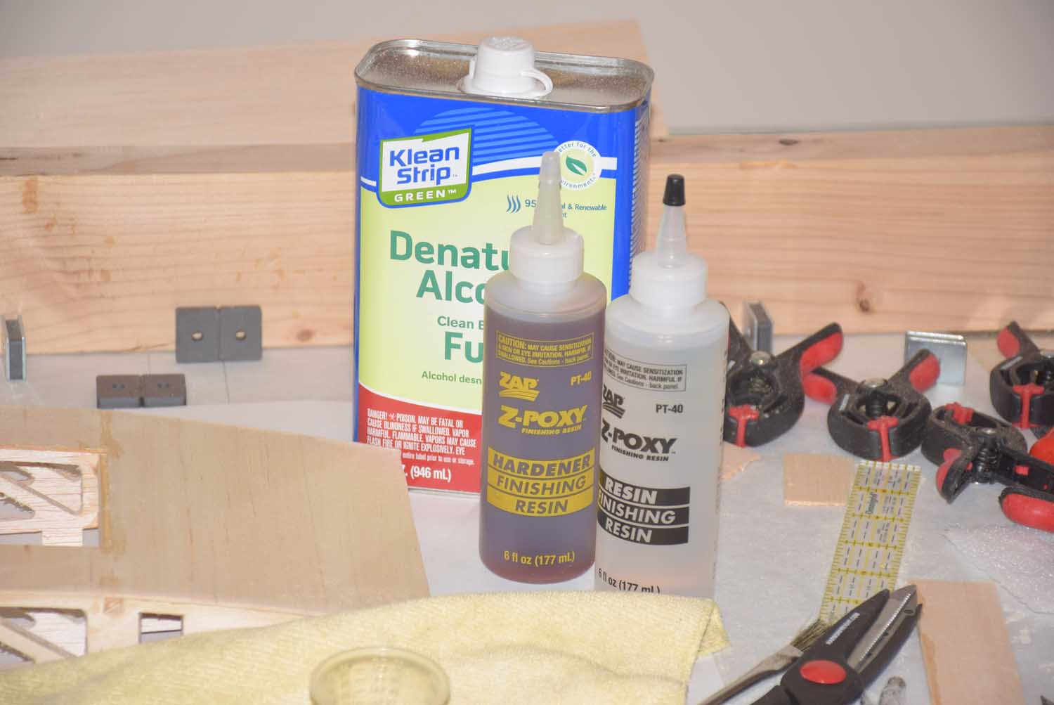
- Thinning the resin helps it to soak into the wood a little more and makes it more smooth.
-
- Cutting fiberglass to slightly over-sized.
-
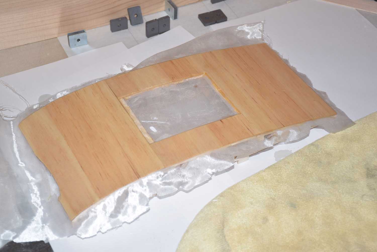
- Once dry use sand paper to remove the extra.
-
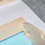
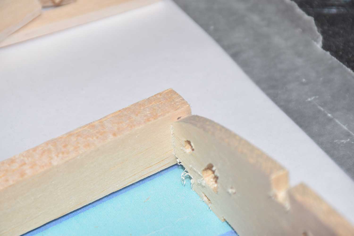
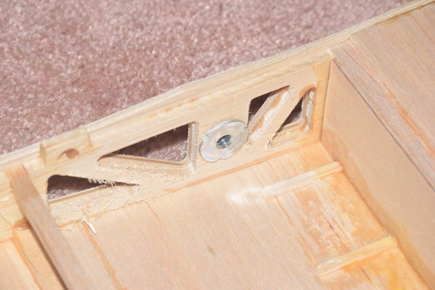
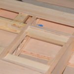
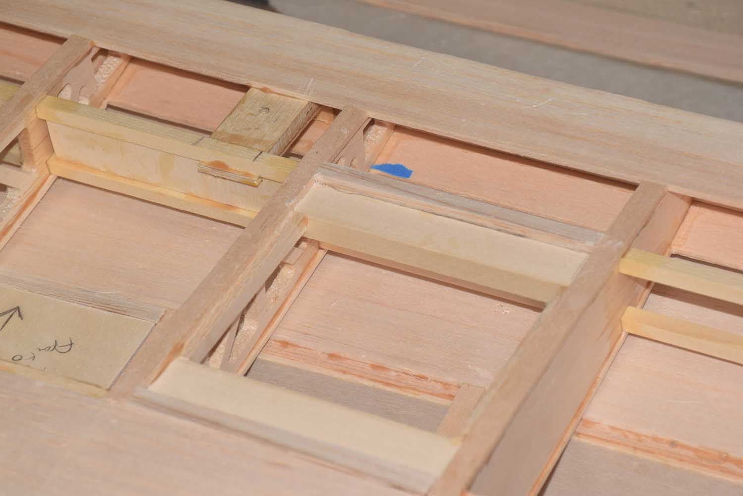
- Adding some additional bracing for where the bold holes will go.
-
- Fiber glassing the bottom of the wing center section – will remain un-covered.
-
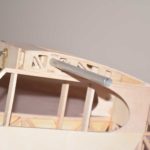
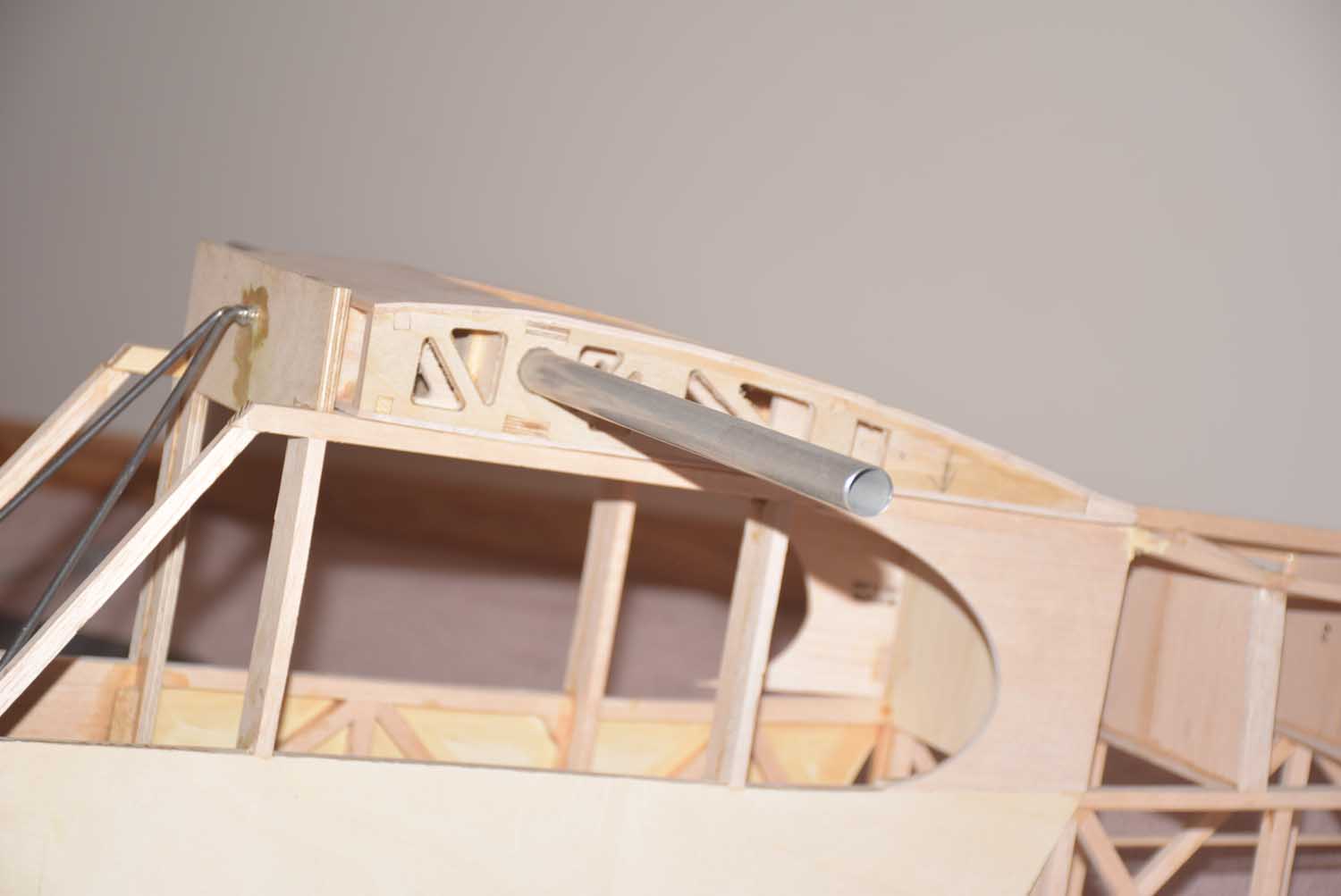
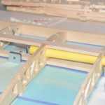
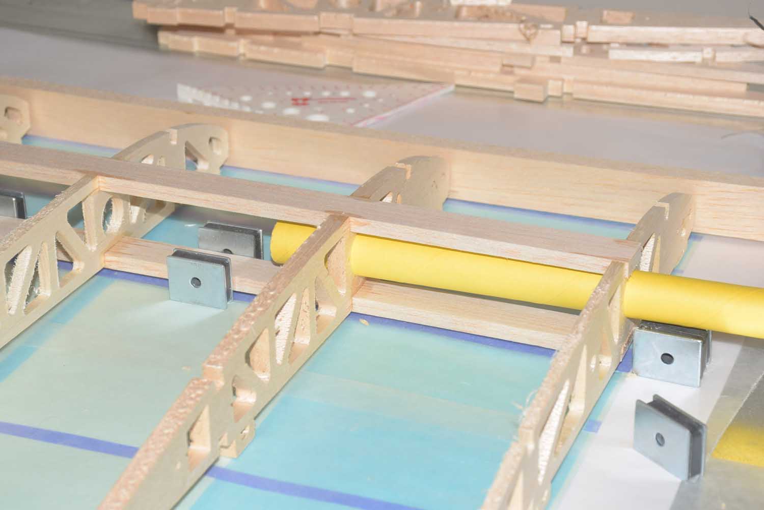
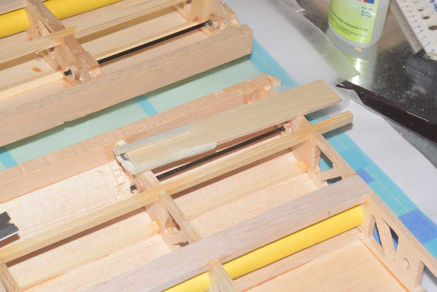
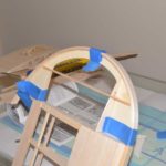
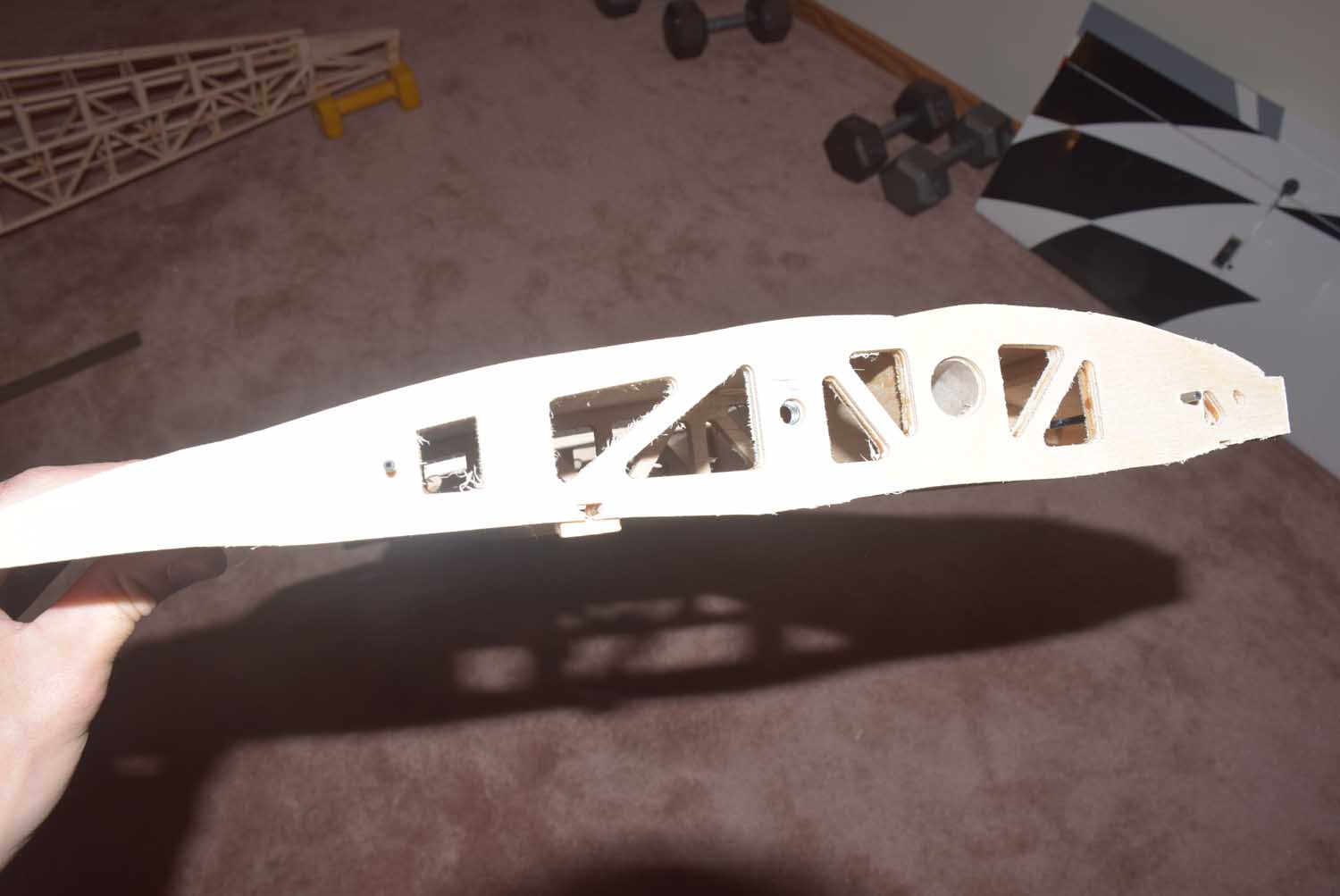
- Trial fit of wing tube and bolt on section!
-
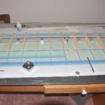
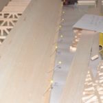
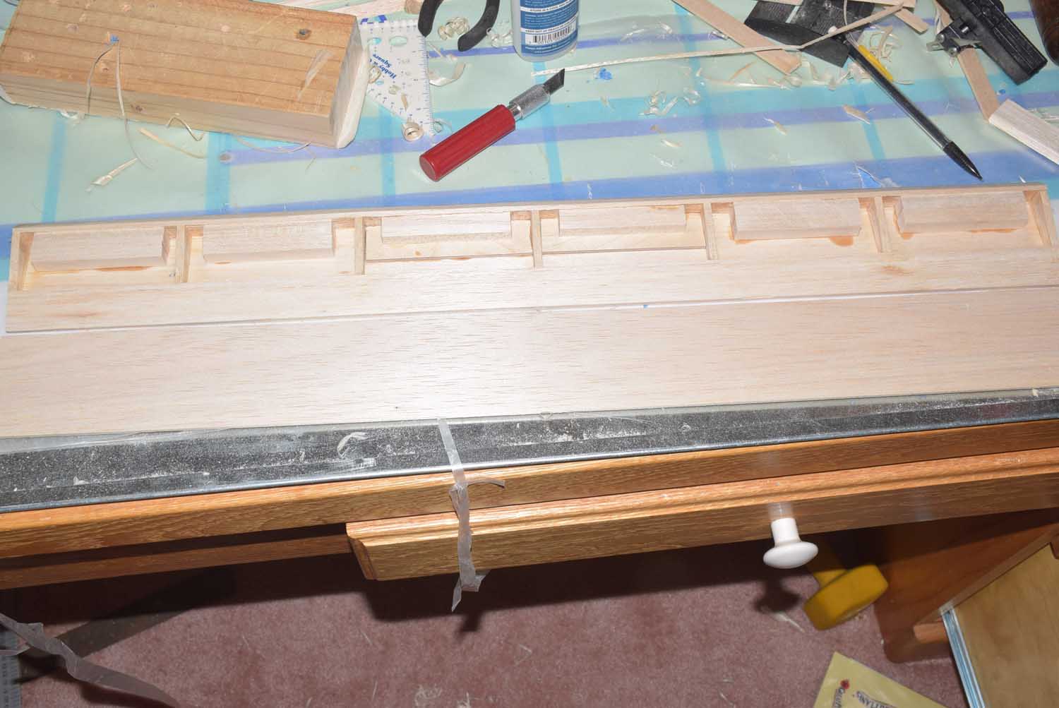
- Wider shot of rib placement and spars.
-
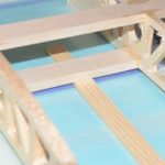
- Getting spars in place.
-
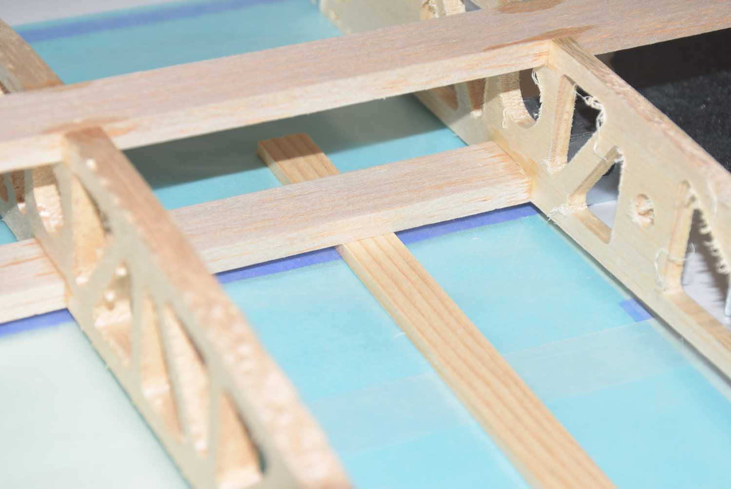
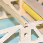
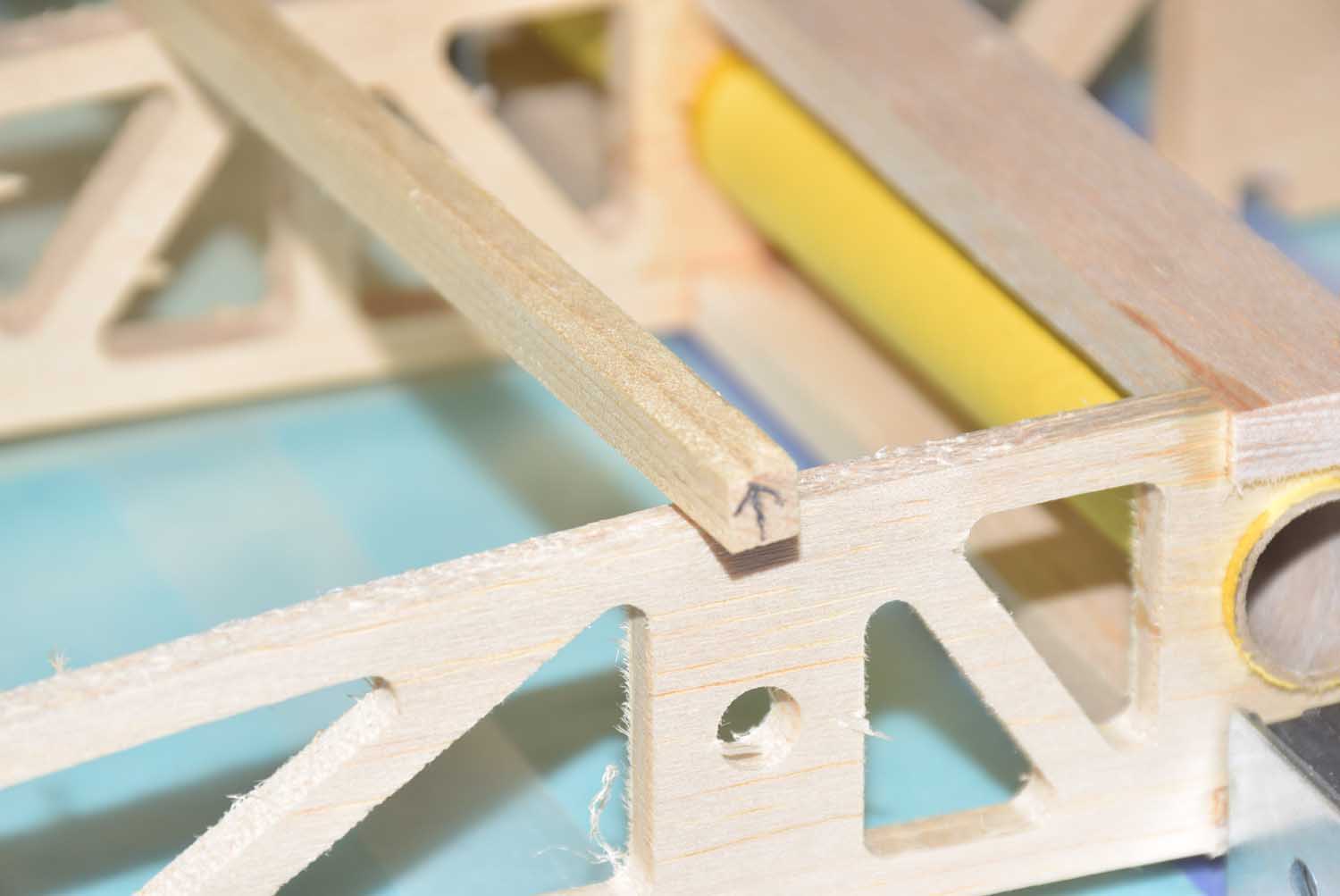
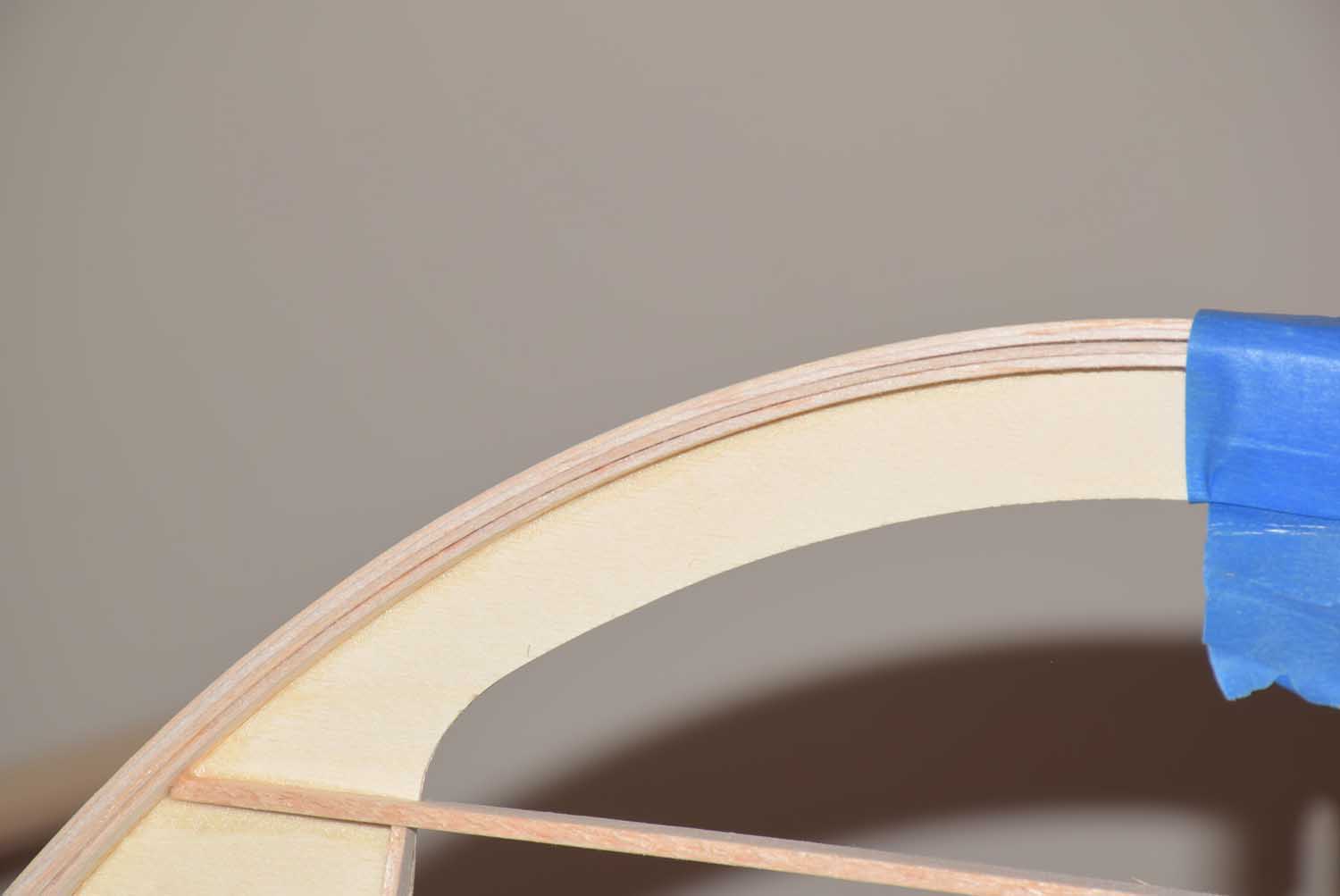
- Inserting the wing tube into the first three rib locations. Notice the dihedral is built in properly!
-
- Leading edge.
-
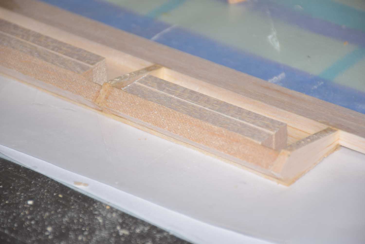
- 1/4 inch spruce spar. Notice the holes for the wing bolts to bolt on to the center section. 1/4 x 20 Blind nuts will go here.
-
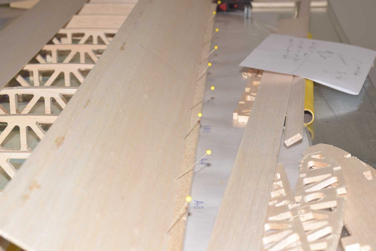
- Pin the spars in place if needed.
-
- Getting sheeting in place.
-
- Getting sheeting in place.
-
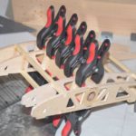
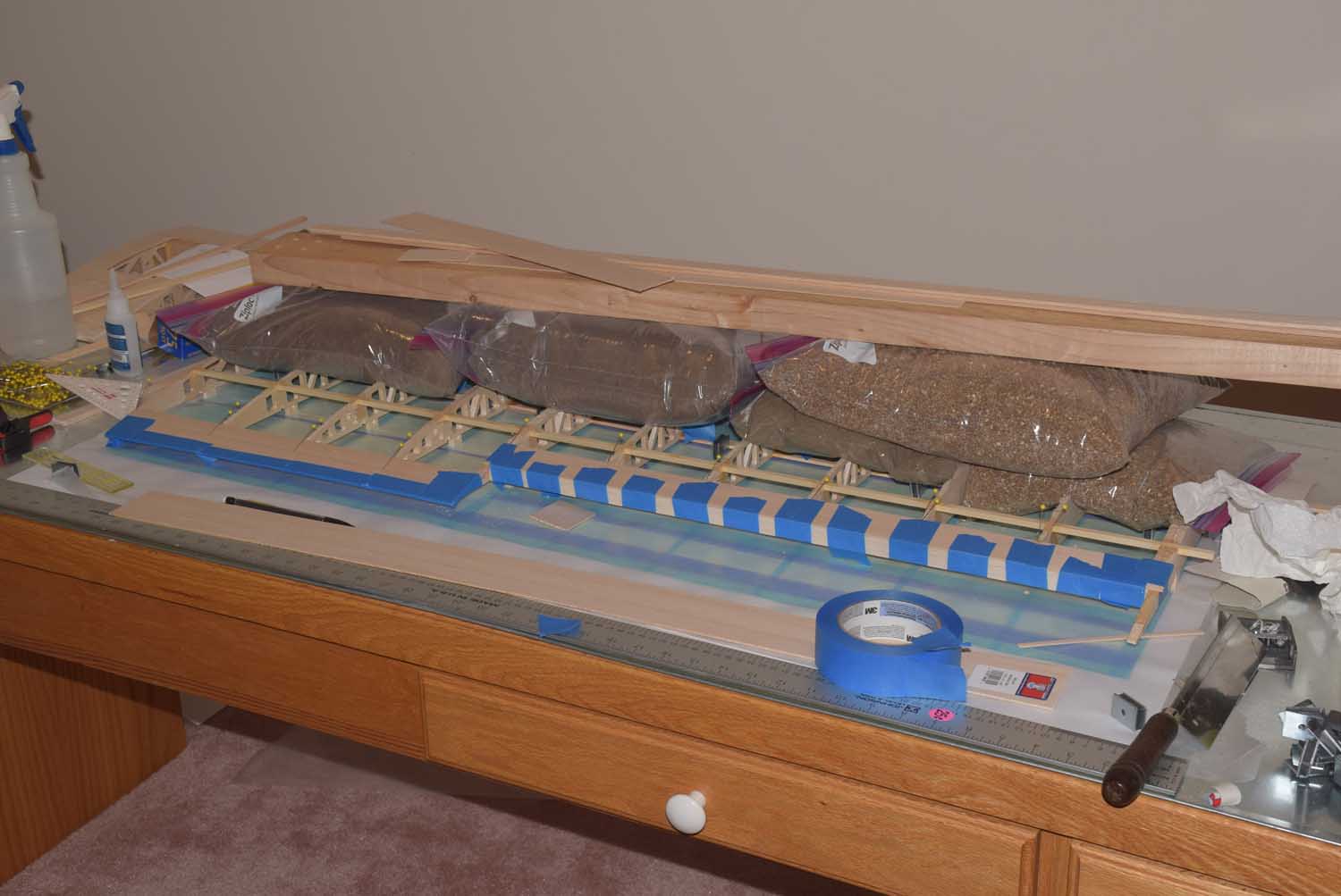
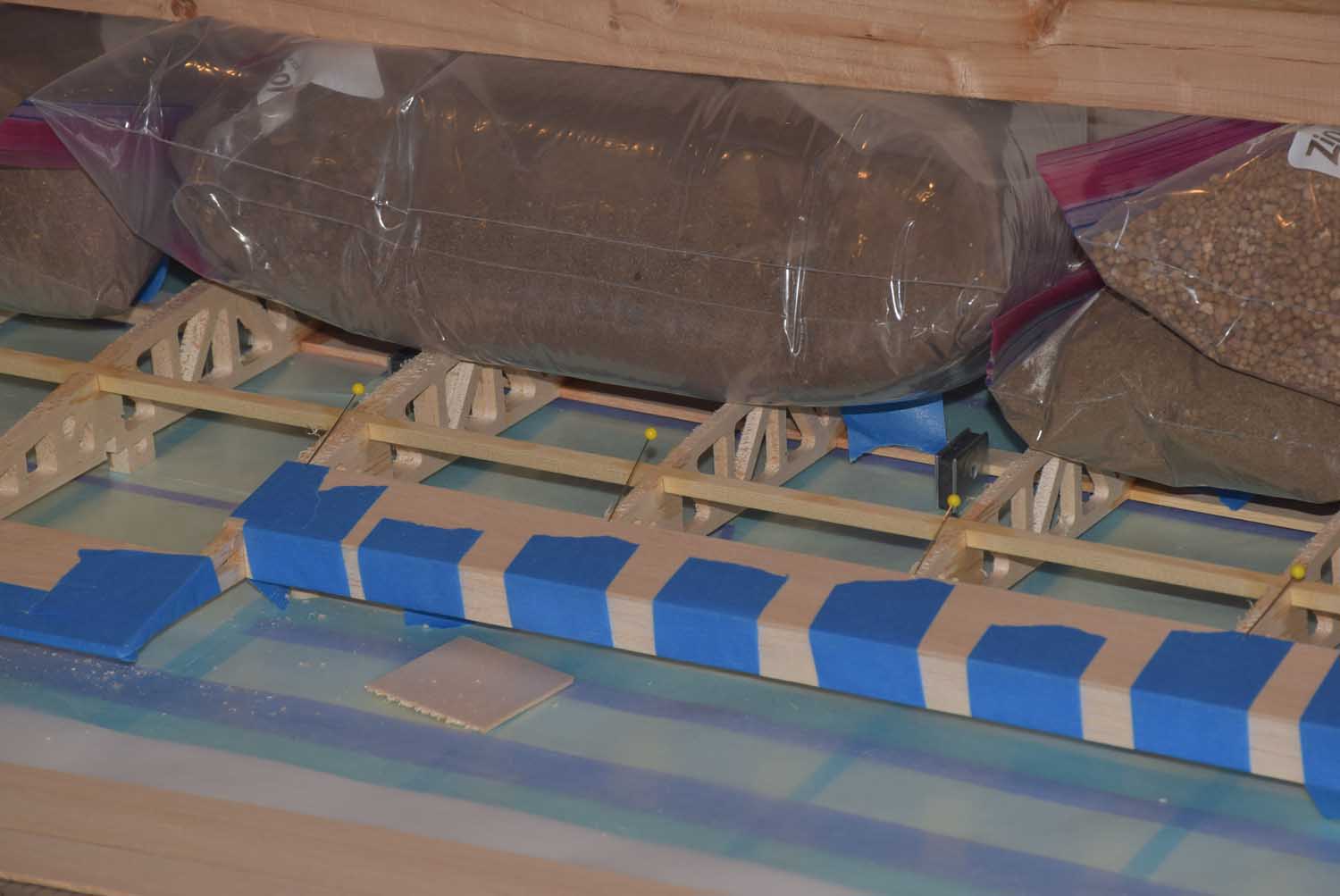
- Letting it all dry!
-
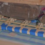
- Letting it all dry! Use sand bags and clamps where needed.
-
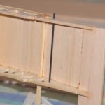
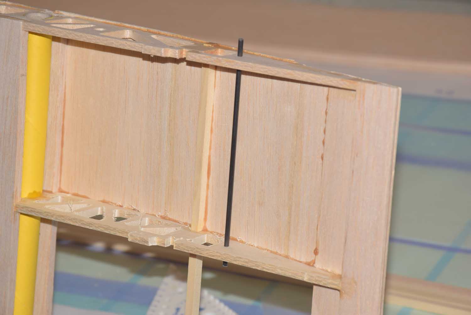
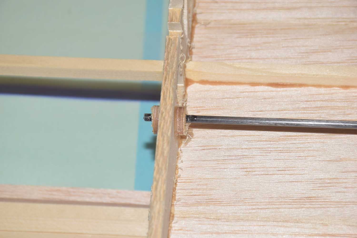
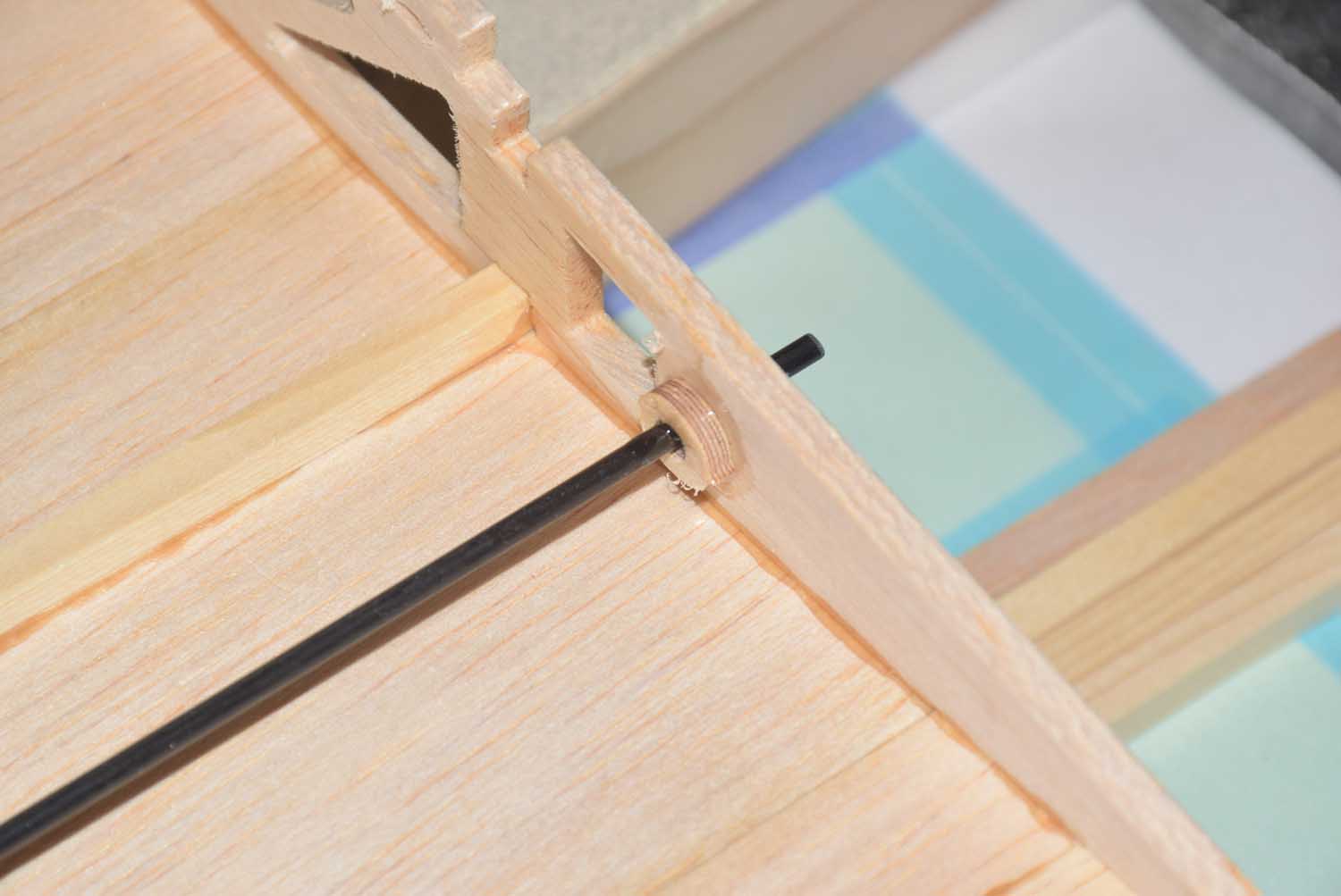
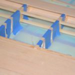
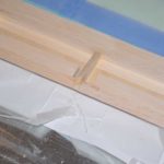
- Anti rotation locations using some carbon tubes I had.
-
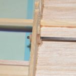
- CNC cut 1/8 play braces to secure tubes in place.
-
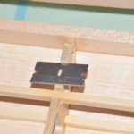
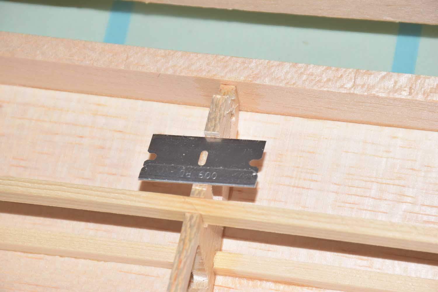
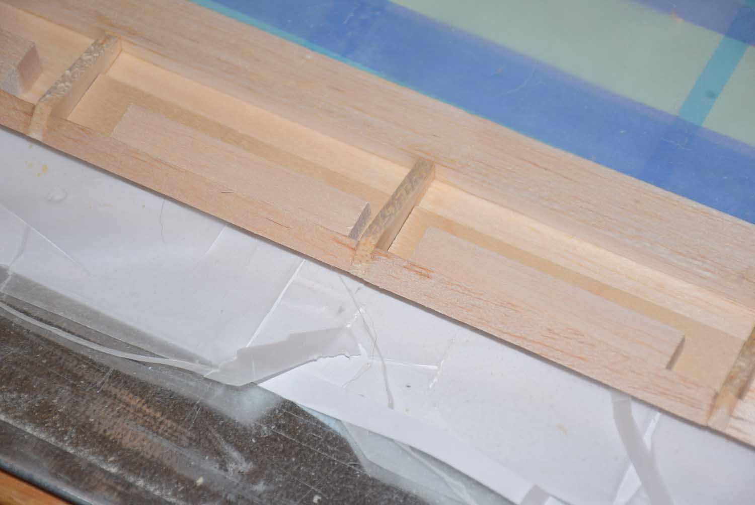
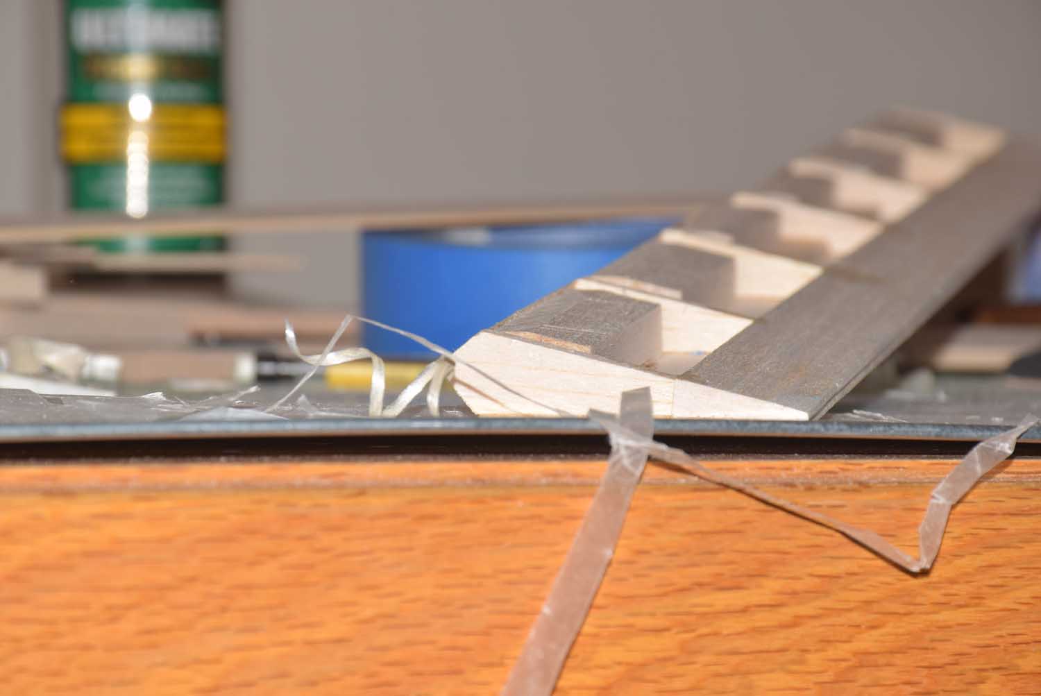
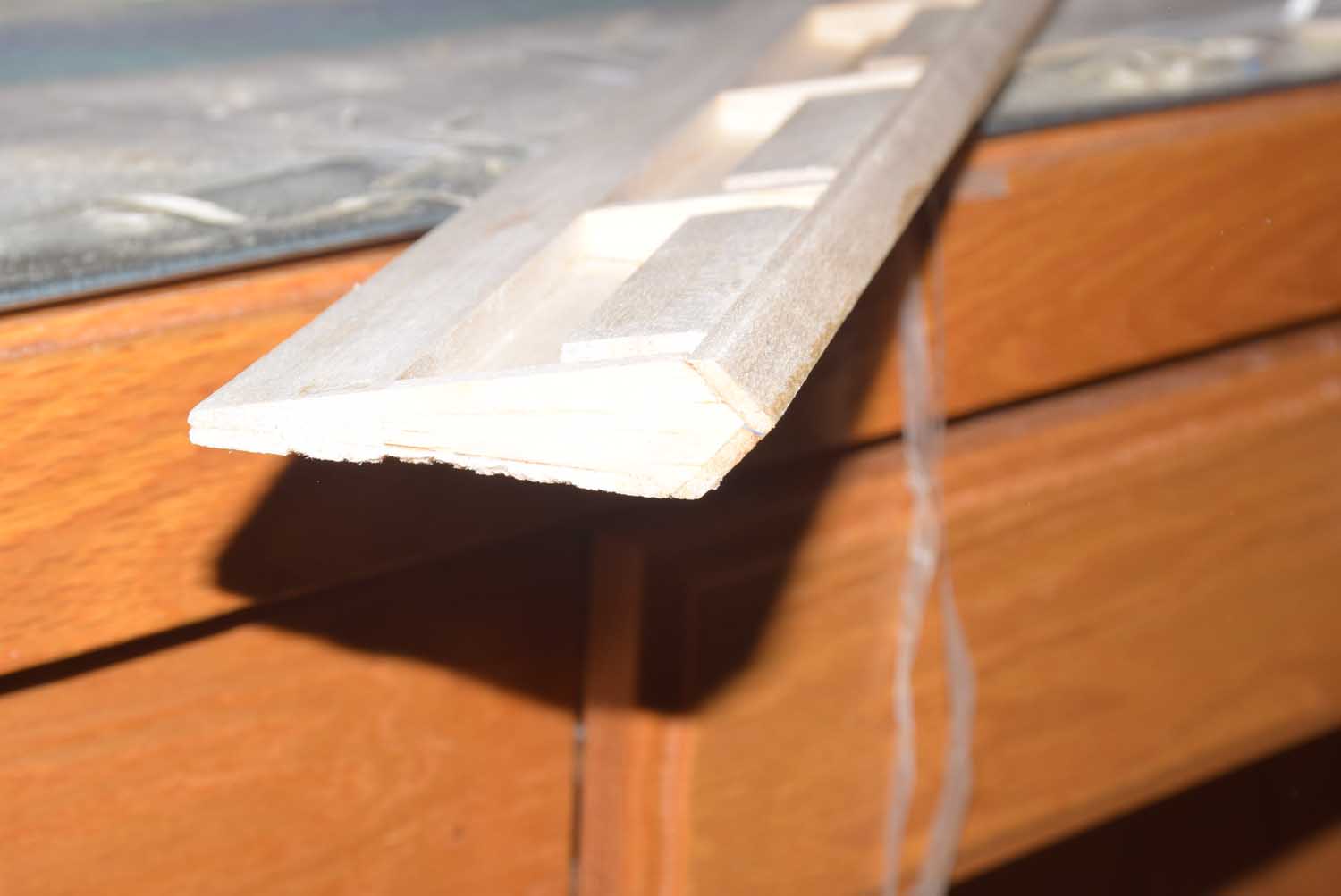
- Trimming off the tabs so I can sheet the bottom of the wing.
-
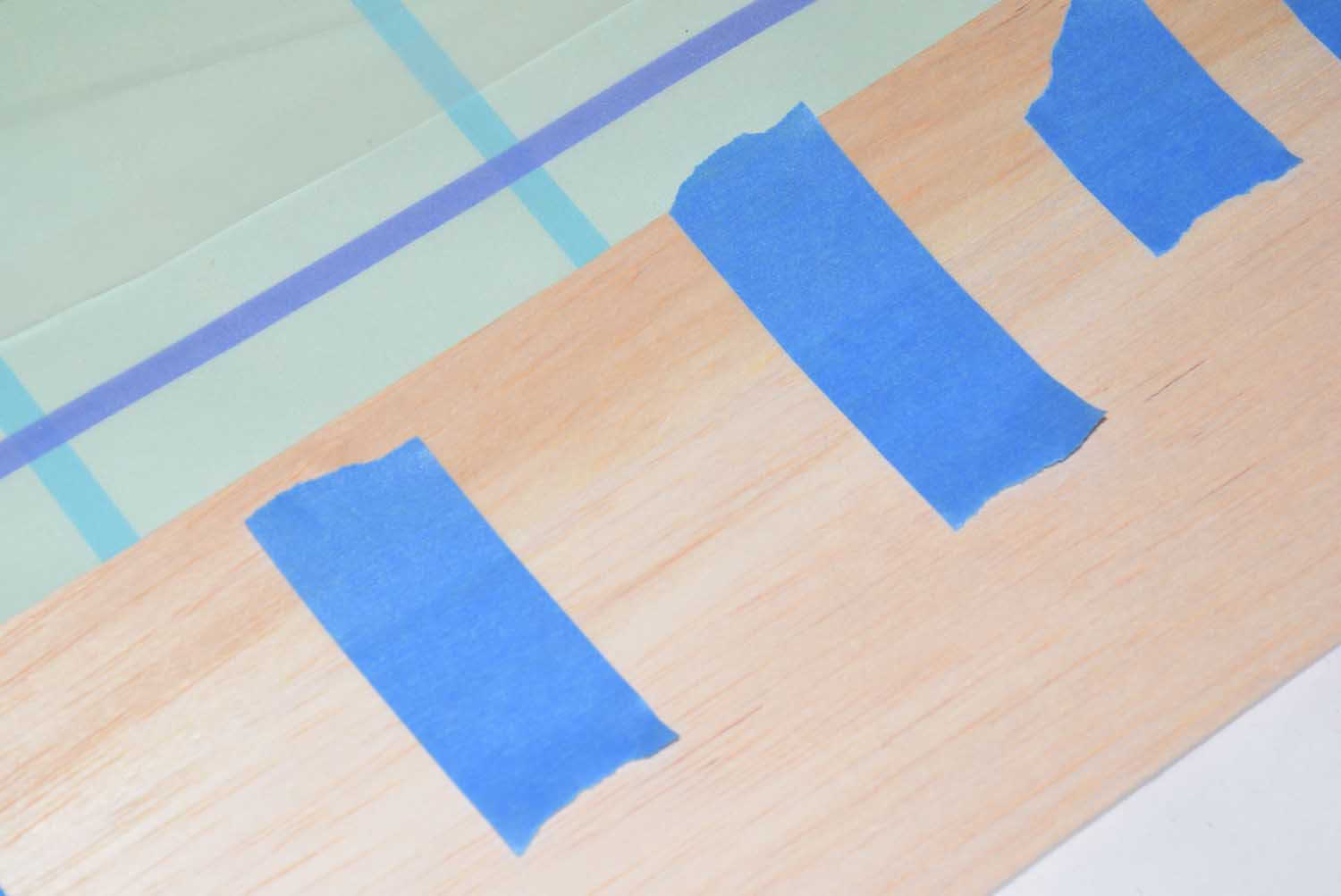
- Use tape to glue seems together for larger sheets.
-
- Using the wing tips included with the kit. Follow instructions in the manual.
-
- Using the wing tips included with the kit. Follow instructions in the manual.
-
- Getting spar webs in place.. tape helps to hold securely.
-
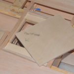
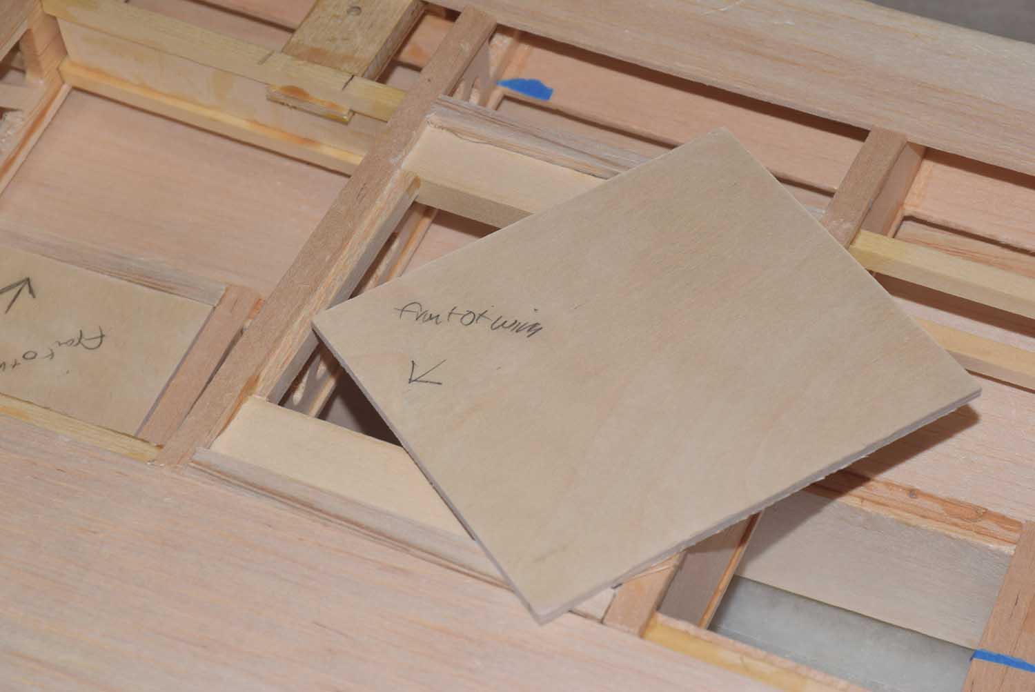
- A rough-cut outer ply rib cap… sand to fit contour of wing.
-
- A rough-cut outer ply rib cap… sand to fit contour of wing.
-
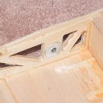
- Be sure the blind nuts for the wing bolts are in place before your completely close it up!
-
- Clamp the outer ply cap rib.
-
- Adding cap strips.
-
- Building up of the ailerons as designed by DevWing program
-
- Building up of the ailerons as designed by DevWing program
-
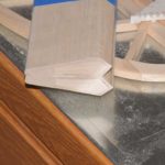
- Some shaping on the fill in blocks
-
- Some shaping on the fill in blocks
-
- Some shaping on the fill in blocks
-
- Completed ailerons.
-
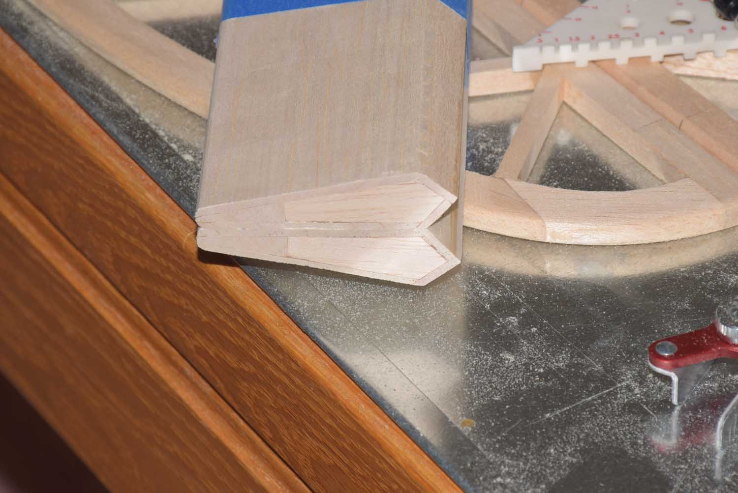
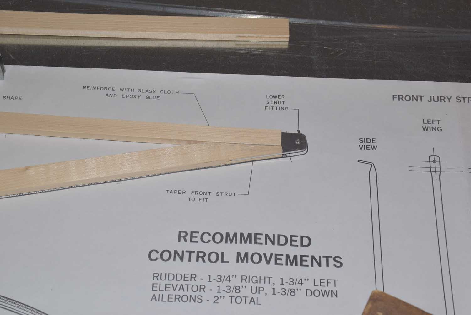
- Building the included wing struts as per instructions in the manual.
-
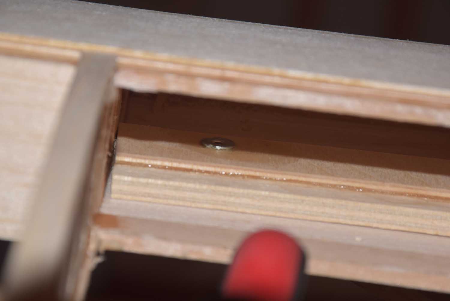
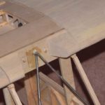
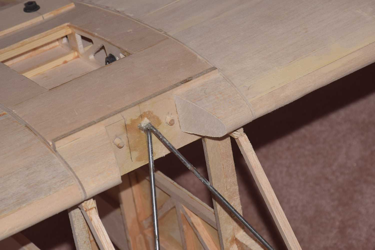
- adding some hard wood mounting locations for the wing struts. I used 4-40 blind nuts here.
-
- adding some hard wood mounting locations for the wing struts. I used 4-40 blind nuts here.
-
- adding some hard wood mounting locations for the wing struts. I used 4-40 blind nuts here.
-
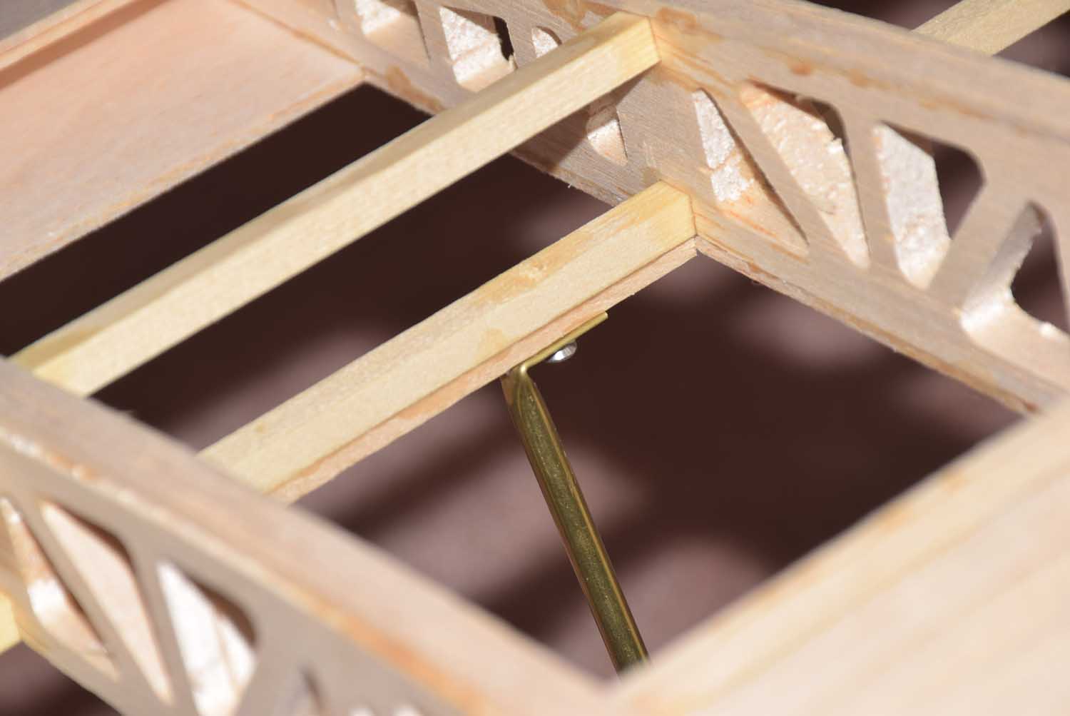
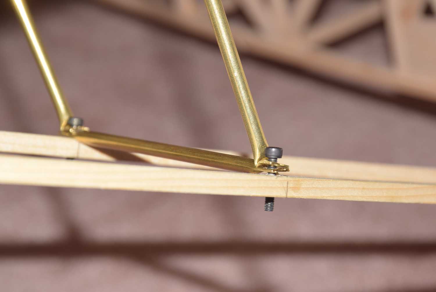
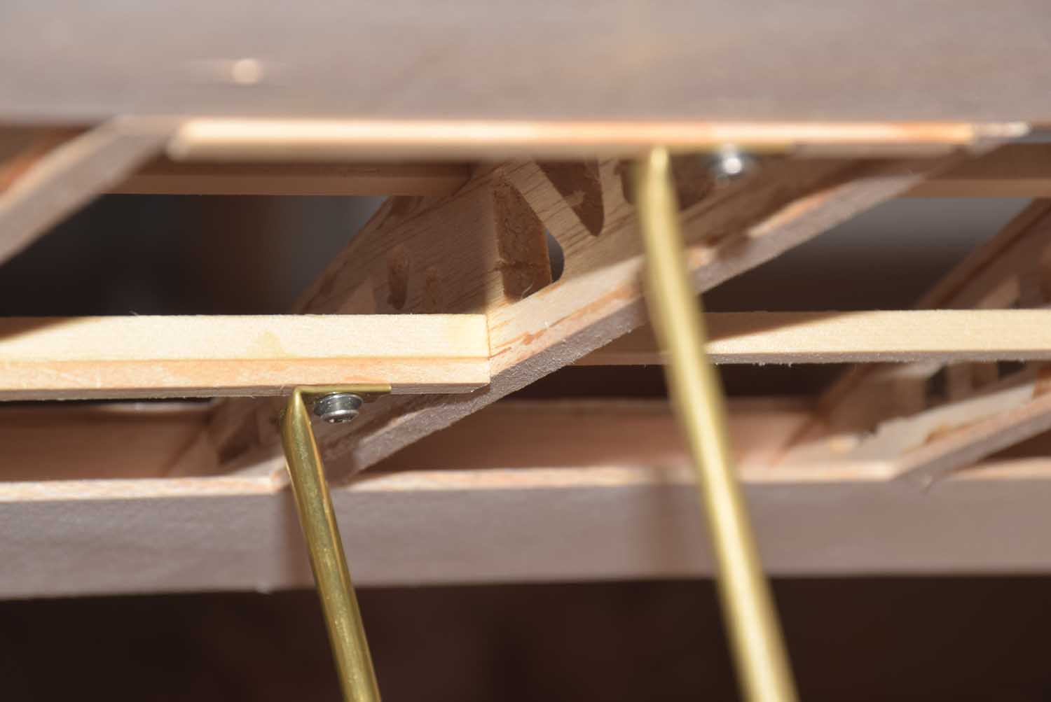
- Test fitting the brass wing strut tubing
-
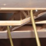
- Test fitting the brass wing strut tubing
-
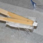
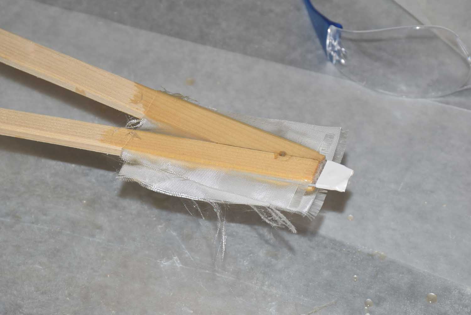
- Glassing the ends of the strips where the bolts will go.
-
- Adding some bracing for the aileron servo locations
-
- Adding some bracing for the aileron servo locations
-
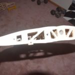
- Test fit the wing!
I will write a separate post showing some screenshots from the DevWing Program.